Fadfae Survey Interfacing
The onboard survey team are connected to the AUV network via ETH3 on the EdgeX router and they have set their IP address to the below, in order to receive telemetry and data feeds from the vehicle.
IPv4 Address: 192.168.200.90
Subnet: 255.255.255.0
Default Gateway: 192.168.200.1
DNS: 192.168.200.1 / 1.1.1.1
If you have any issues regarding the data transmission to the survey team:
- Disconnect them from our network, and change the reports PC IP address to the same as above
- Test the R2sonics/Edgetech on our system, with the installed softare, to confirm operation
Or open NaviPac/NaviScan config and checks comms following this How To - Tell them it's their problem
| IP Address | Protocol | Description |
|---|---|---|
| 192.168.200.135 | UDP | SIM |
| 192.168.200.134 | UDP | Head 1 |
| 192.168.200.136 | UDP | Head 2 |
| 192.168.0.244:20501 | UDP | Output - Sonardyne LNAV via Saab mirror ports |
| 192.168.0.244:30502 | UDP | Output - Parascientific Pressure Sensor via Saab mirror ports |
| 192.168.0.244:40503 | UDP | Output - miniSVS via Saab mirror ports |
| 192.168.0.221:4001 | TCP | Output – PD6 DVL data |
| 192.168.0.222:4093 | UDP | Output - Sonardyne LNAV output – direct from SPRINT-nav |
| 192.168.0.223:18055 | UDP | Output - GGA & ZDA direct from onboard GPS card |
Network Data
| Location | Port | Baud Rate | Description |
|---|---|---|---|
| SAC | 3 | 9600 | Input - USBL $PSIMSSB |
| 3 | 9600 | Output - TSS660 | |
| Perle | 2 | 115200 | Output - FIGS 2 |
| 1 | 115200 | Output - FIGS 1 |
Serial Data
Wiring Diagram
The below image shows a very simplified schematic of the wiring onboard.
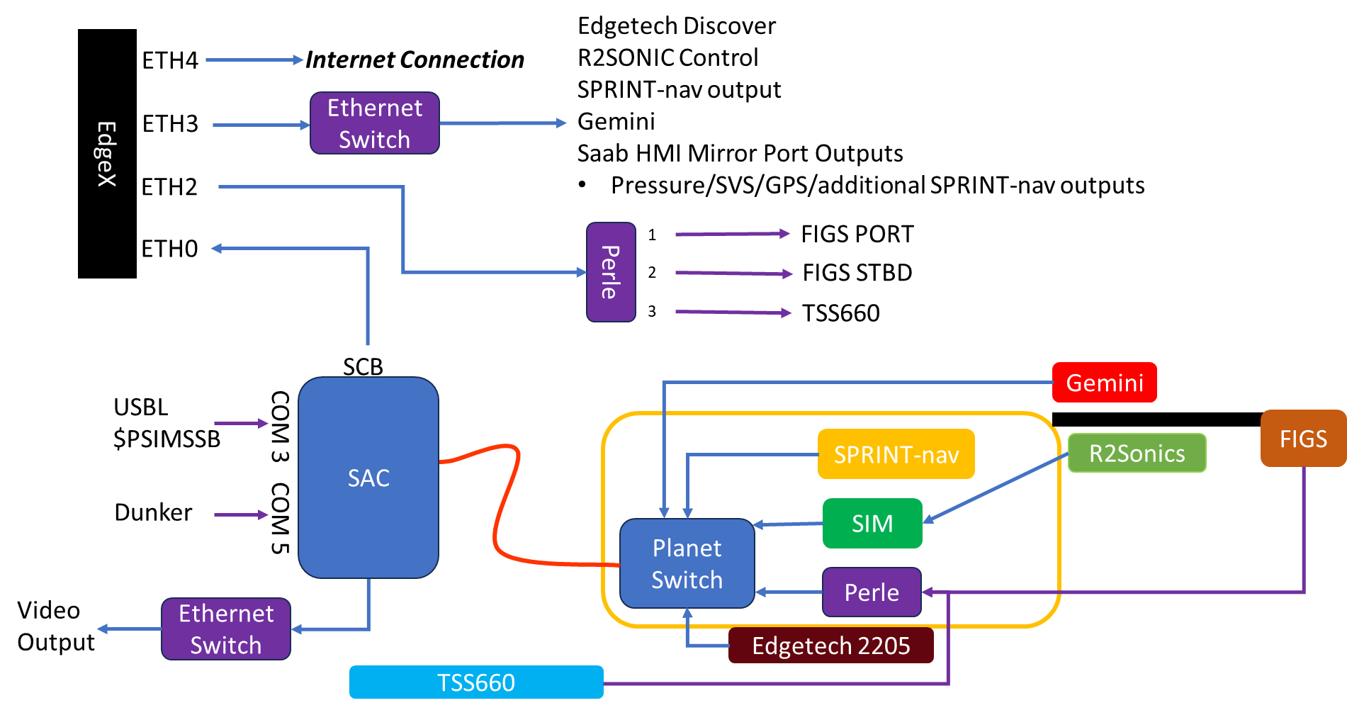
Simplified Wiring Diagram
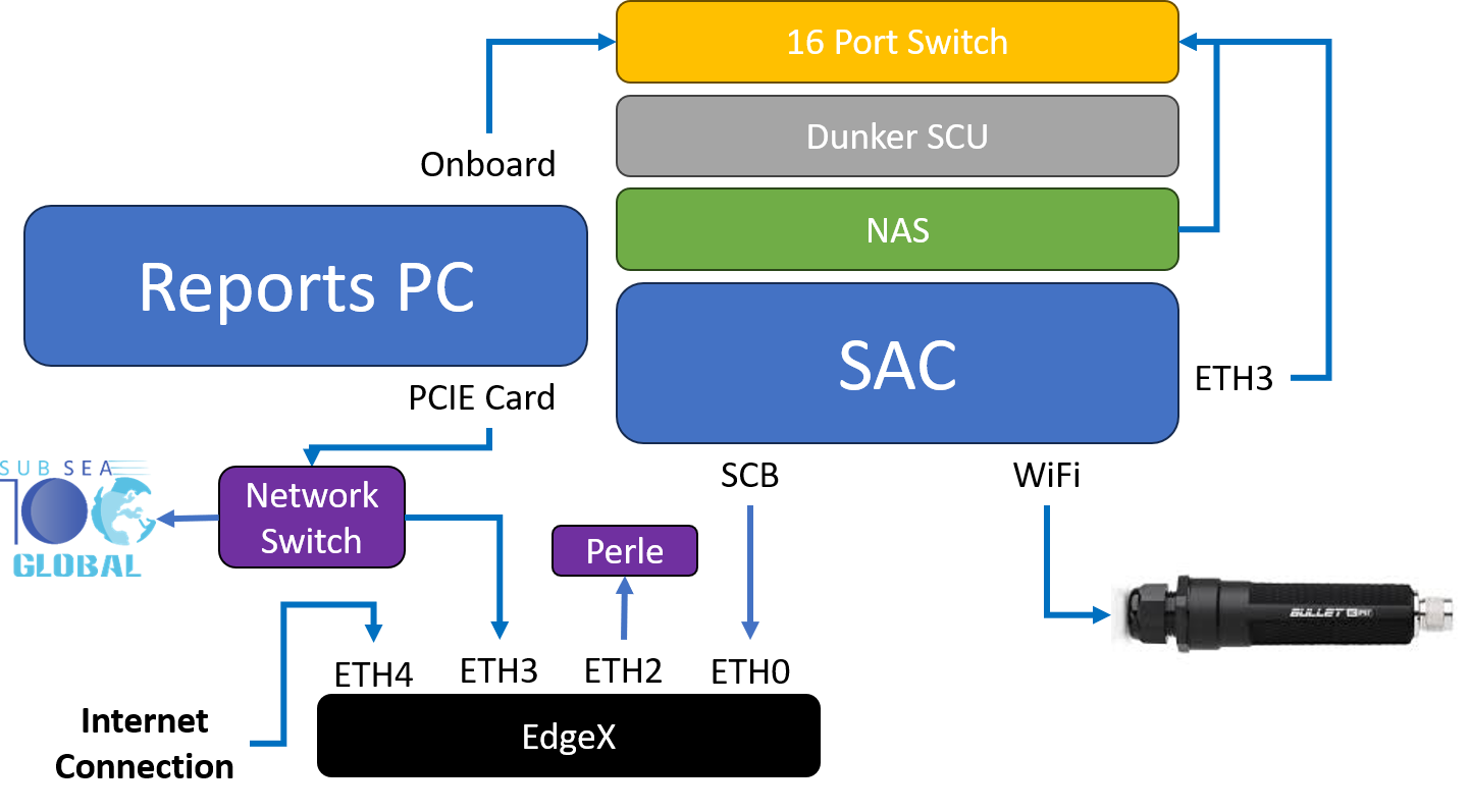
Control Cabin Network Connections
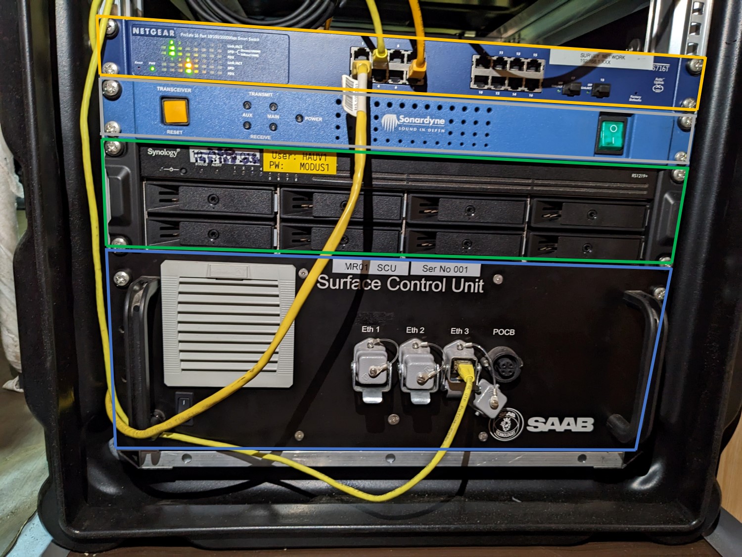
SAC Box
Note that all our network cables are yellow, different colours are for other departments
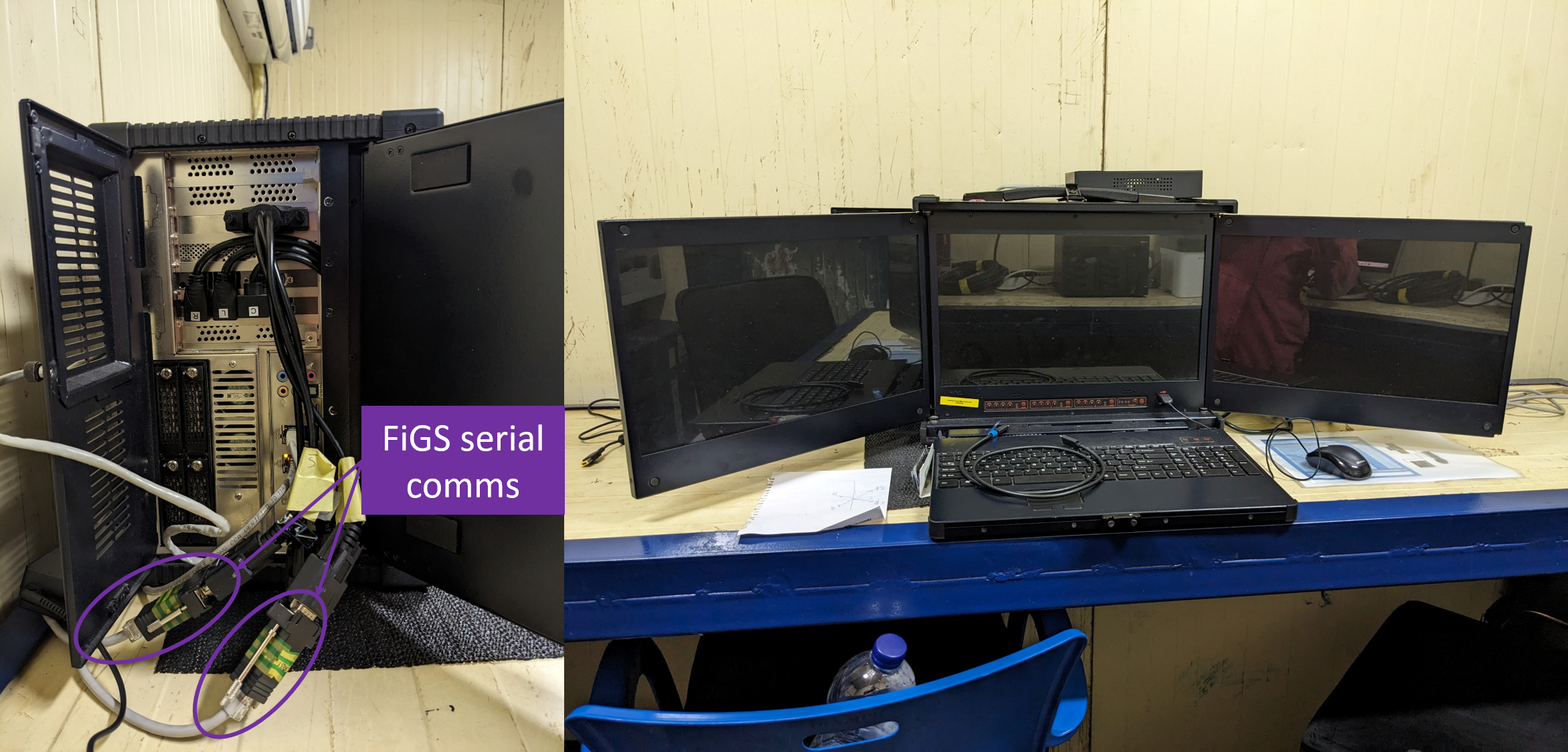
Survey Interfacing & MOXA
4 network cables and 1 serial cable have been ran between the survey container and our control cabin, it is the grey/white cables and they have all be labelled.
Network Cable 1 = Data transmission from vehicle (vehicle data, video and MBES)
Network Cable 2 = Edgetech (Survey aren't the best and they have network issues, meaning they couldn't see the SSS data and are running discover on a separate computer now)
Network Cable 3 = Survey MOXA
Network Cable 4 = Gemini (HDMI to RJ45)
Serial cable = USBL direct from the GAPS system.
We have a Nport 5410 on the cabin, this has been supplied by survey. This is for them to receive the TSS660 data and us the Vessel position which is being displayed in the tactical view.
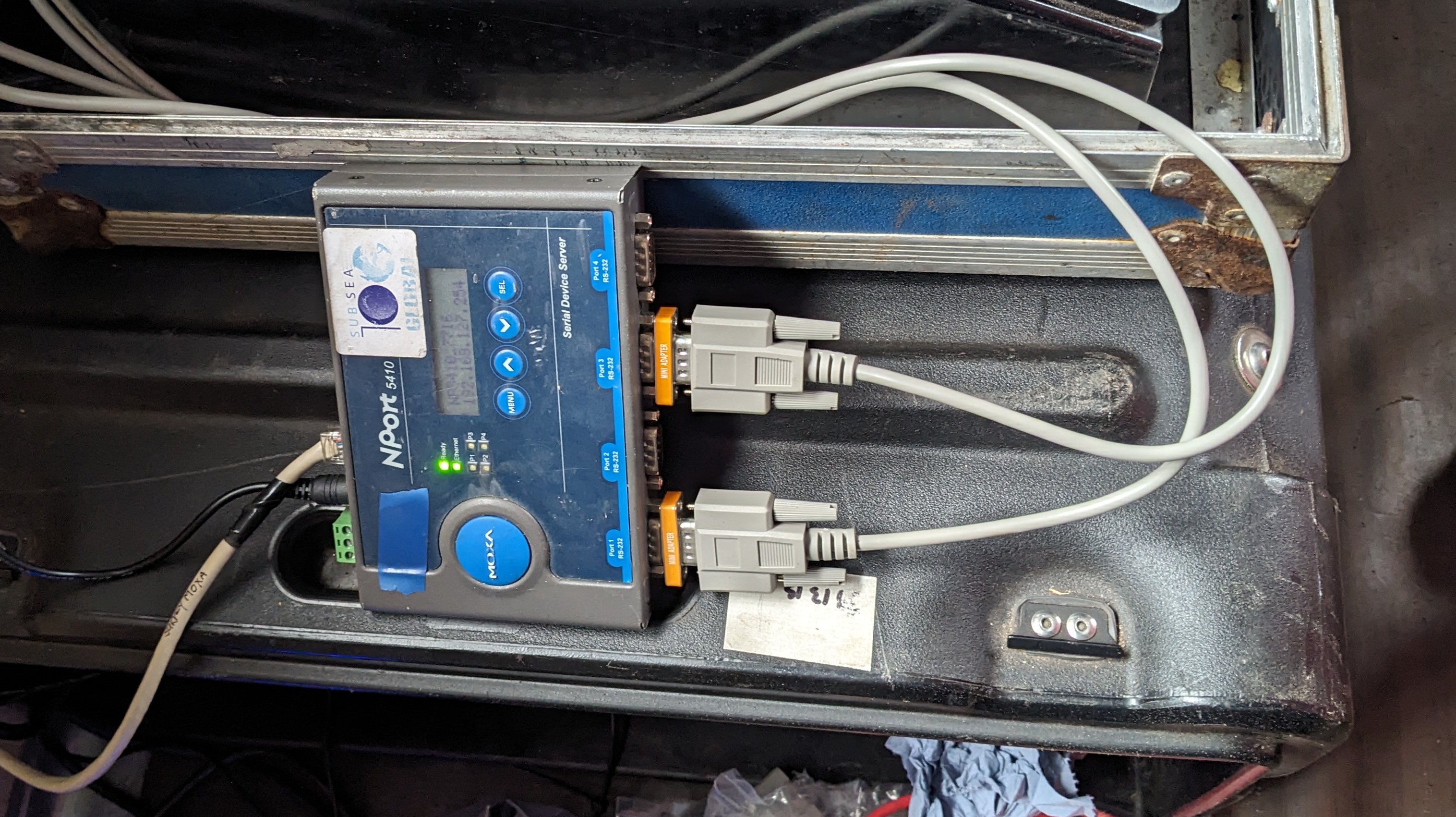
MOXA
Perle Serial to Ethernet Device Servers
The topside Perle server is located between the TSS and SAC, and is connected to ETH2 on the EdgeX. Connection to the unit is done via web broswer on the the Reports PC, IP Address and passwords can be found in the Vehicle IP Listing.
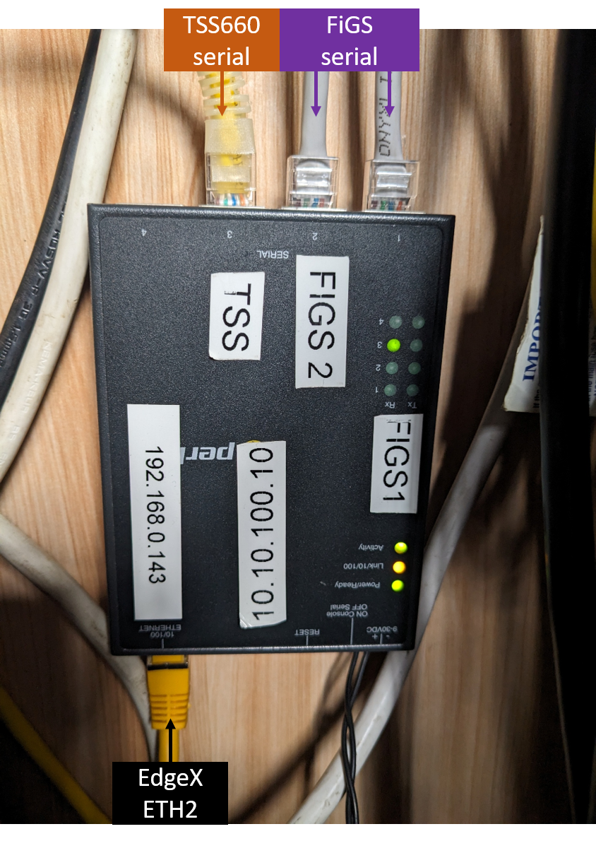
Perle Server
FIGS
Both FIGS sensors are connected to B3 on the STBD FWD pod lid using a Y splice, these connect into Port 1 & 2 of the Perle server (144) in the pod. Data is passed directly to the unit in the Control Cabin (143). Where it has been routed to the FIGS specialists, who are housed in the client reps container.
FIGS Setup
TSS660
The TSS660 is connected to B2 on the STBD FWD pod lid, this then connect into Port 3 on the Perle server (144). The Data is passed directly to the unit in the control Cabin (143) and connected to COM 2 on the TSS topside unit. The data is output from COM3 and goes into Port 1 on the Survey MOXA. The topside has been deposited in our container, and placed on top of the Reports PC. A HDMI cable is ran to the pilots desk for a repeat of the screen for flying. Survey will be operating the unit, doing the background comps and setting any of the scaling etc and energising the coils prior to commencing surveys. After talks with Fadfae, apparently they were assuming that I will be manning the pipetracker as none of their guys know how to use it. That is why I am here apparently, apart from we specifically had a meeting in regards to this and I was here to help, interfacing, advise even train, but not here to do their jobs for them. I have written a short training document to give everyone a rough guide to it's setup, calibration and operation, including some fault finding notes.
Do not energise coils when people are working on or near the vehicle
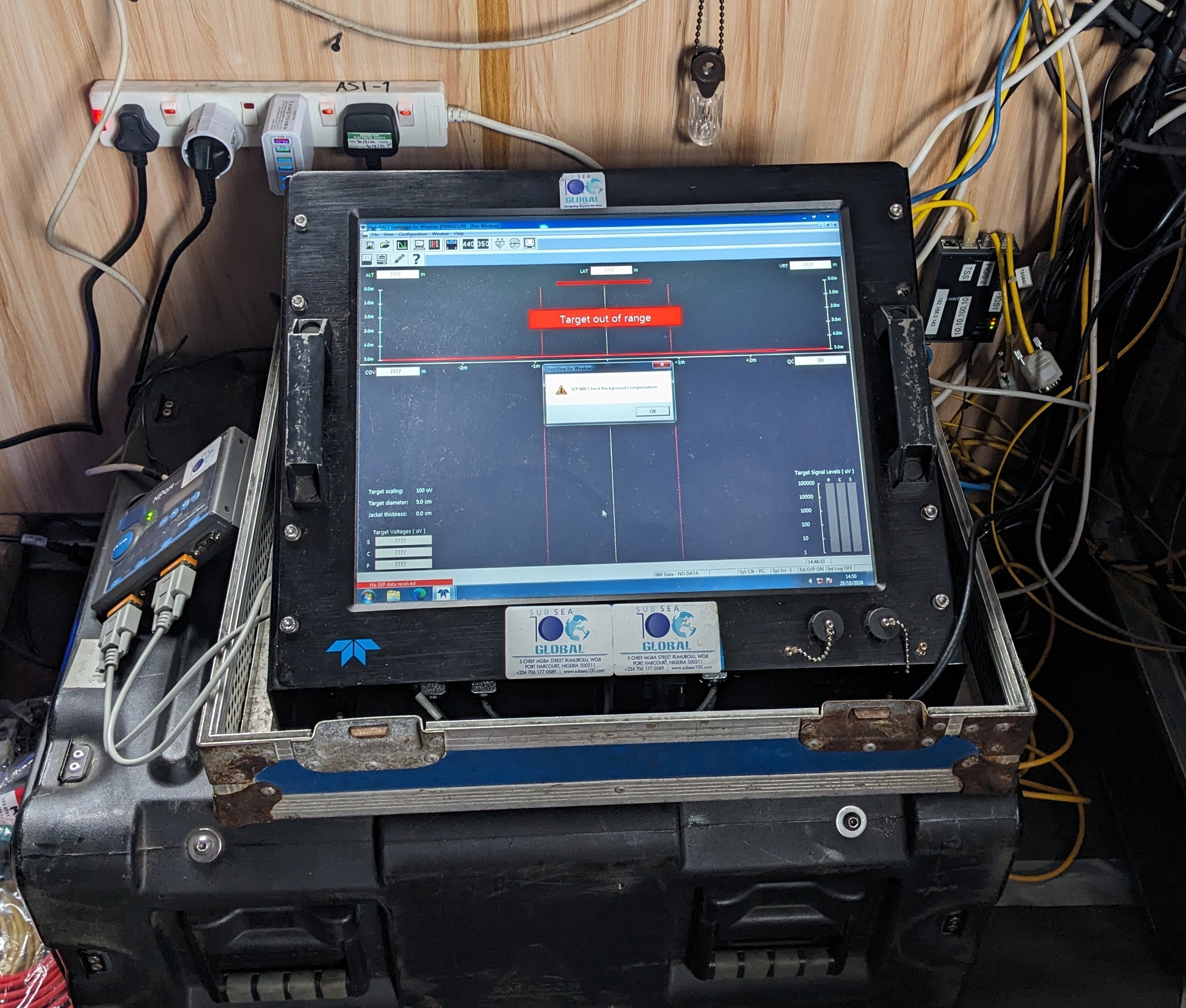
TSS660
Gemini
The Gemini is being ran on a laptop in front of the main pilots screen. Survey were planning on having a repeat of the screen in there container, hence the network cable witha ring of blue tape, but they don't have a HDMI to RJ45 extender or spare screen.....so why they requested it in the first place I don't know?
The IP Address can be found in the Vehicle IP Listing.
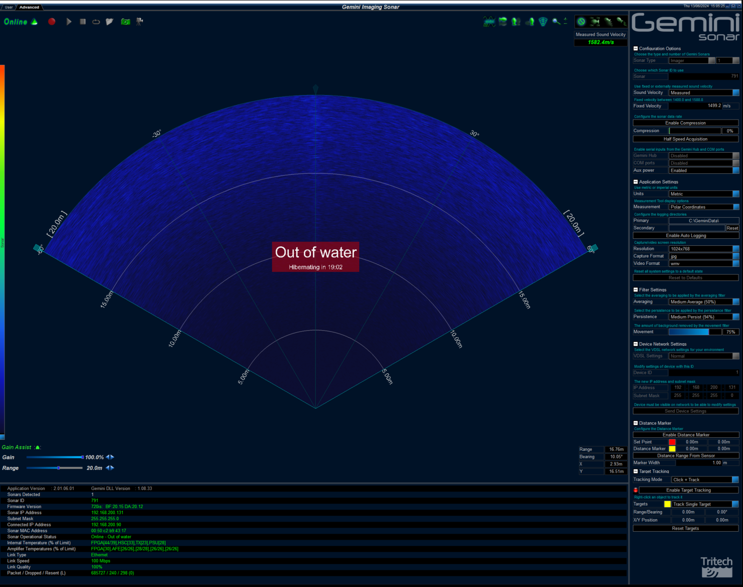
Gemini
Valeport 106 - Current Meter
At the last minute, we have received a Valeport 106 - Current Meter. The unit is still missing the power supply for the CDU and the CDU to reel link cable, but can be operated by a single D cell battery...which we have 2 off currently. Survey have setup a serial input on there online PC for this and I have requested that it gets displayed in the NAV screen, plus recorded into their blackbox logging....once they have set it up. The survey may need some help with deployment, which will likely be the Port Aft vessel corner, where survey conduct the sound velocity cast. I would suggest only deploying it when the vessel is stationary, e.g. Deployment/Recovery, BGCs etc, surveying at 2knts with it in the water will give false readings and could be dangerous.
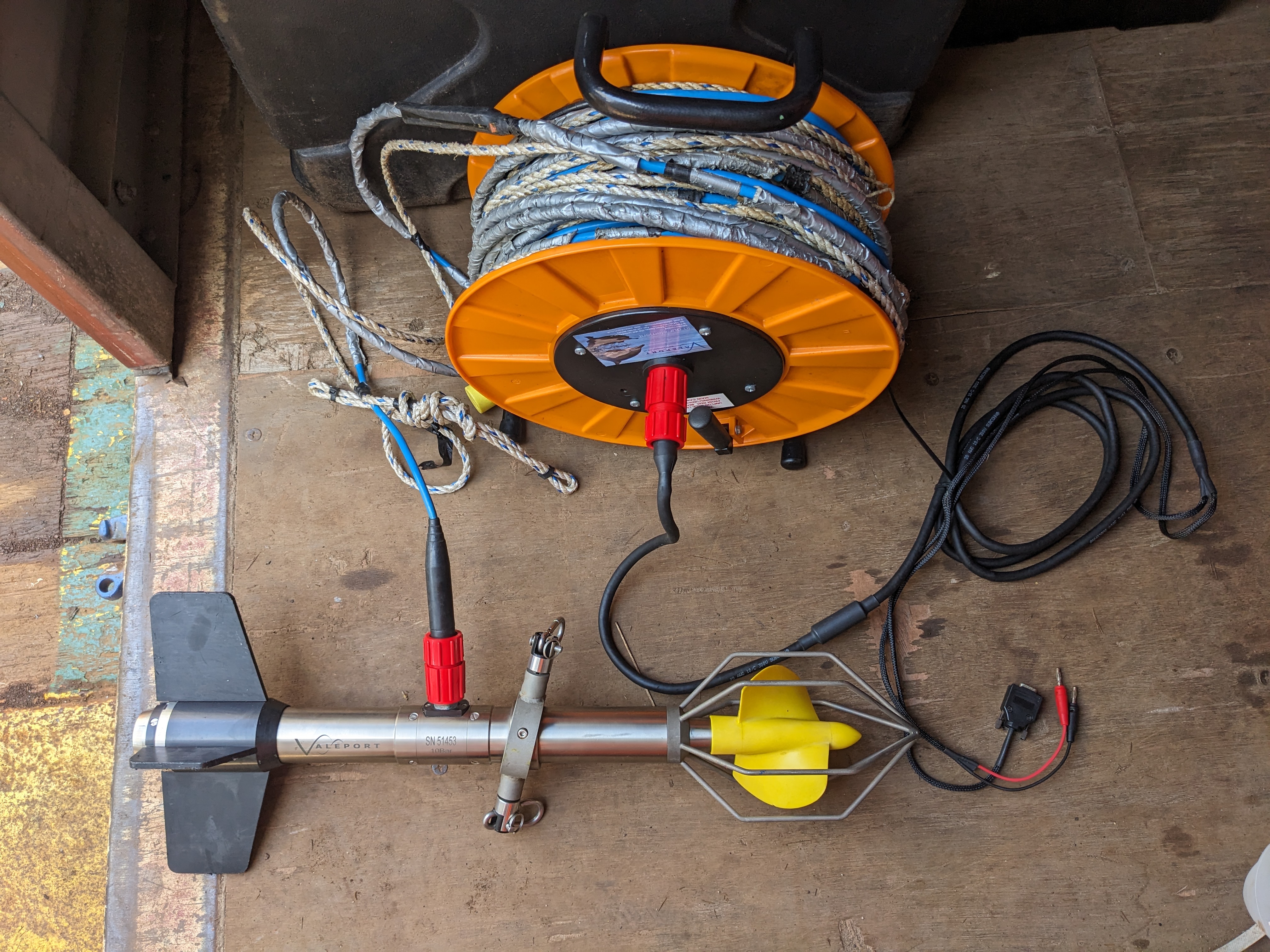
Valeport 106 and Reel
Serial setting
Baud rate: 4800
Data bits: 8
Parity: None
Stop bits: 1
Flow control: none
Navigation Screen
Rather than having a remote Helmsman, and the ability to control our own nav screen, the survey department have decided to just give us a repeat of the survey screen. This is less than ideal, but they have
Trigger Settings
Very little direction from survey on this, I have looked at the PEP and Shell Requirements.
From what I can discern, 50cm cell size with 9 hits per bin - which is 18Hz and SSS at 5Hz should be fine. After talking to survey, I have suggested they just use the internal triggers on both units, if we see any degraded DVL performance this will need addressing.
| Sensor | Period | Offset | Active |
|---|---|---|---|
| DVL | 200 | 50 | 20 |
| R2Sonics | 50 | 20 | 10 |
| Edgetech | 200 | 20 | 10 |
Trigger Settings
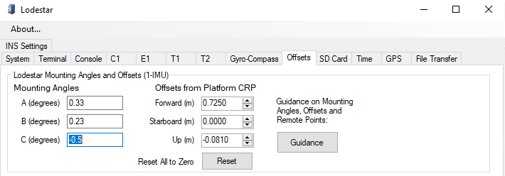
Dimcon Results
On the 10th October 2024, Fadfae conducted a dimcon of the vehicle at Brawal Jetty, Nigeria. We didn't receive the results until 26th October, we have zero idea what took them so long and they didn't even measure the C-Os. So, we are using the results from Sunderland earlier this year. The below screenshot shows the current settings as of 28th October 2024.
C-Os
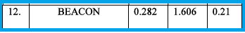
Subsea100 Offsets